Transformers » Types and applications
Types and Applications of Transformers
The transformer has many useful applications in an electrical circuit. A brief discussion of some of these applications will help you recognize the importance of the transformer in electricity and electronics.
Power Transformers
Power transformers are used to supply voltages to the various circuits in electrical equipment. These transformers have two or more windings wound on a laminated iron core. The number of windings and the turns per winding depend upon the voltages that the transformer is to supply. Their coefficient of coupling is 0.95 or more.
You can usually distinguish between the high-voltage and low-voltage windings in a power transformer by measuring the resistance. The low-voltage winding usually carries the higher current and therefore has the larger diameter wire. This means that its resistance is less than the resistance of the high-voltage winding, which normally carries less current and therefore may be constructed of smaller diameter wire.
The typical power transformer has several secondary windings, each providing a different voltage. The schematic symbol for a typical power-supply transformer is shown in the following figure. For any given voltage across the primary, the voltage across each of the secondary windings is determined by the number of turns in each secondary. A winding may be centre-tapped like the secondary 350 volt winding shown in the figure. It means to connect a wire to the centre of the coil, so that between this centre tap and either terminal of the winding there appears one-half of the voltage developed across the entire winding. Most power transformers have coloured leads so that it is easy to distinguish between the various windings to which they are connected. Carefully examine the figure which also illustrates the colour code for a typical power transformer. Usually, red is used to indicate the high-voltage leads, but it is possible for a manufacturer to use some other colour(s).
FIGURE
There are many types of power transformers. They range in size from the huge transformers weighing several tons-used in power substations of commercial power companies-to very small ones weighing as little as a few ounces-used in electronic equipment.
Autotransformers
It is not necessary in a transformer for the primary and secondary to be separate and distinct windings. The following figure is a schematic diagram of an autotransformer.
FIGURE
Note that a single coil of wire is "tapped" to electrically produce a primary and secondary winding. The voltage across the secondary winding has the same relationship to the voltage across the primary that it would have if they were two distinct windings. The movable tap in the secondary is used to select a value of output voltage, either higher or lower than VP, within the range of the transformer.
Audio-Frequency Transformers
Audio-frequency (AF) transformers are used in AF circuits as coupling devices. Audio-frequency transformers are designed to operate at frequencies in the audio frequency spectrum (generally considered to be 15 Hz to 20 kHz).
They consist of a primary and a secondary winding wound on a laminated iron or steel core. Because these transformers are subjected to higher frequencies than the power transformers, special grades of steel such as silicon steel or special alloys of iron that have a very low hysteresis loss must be used for core material. These transformers usually have a greater number of turns in the secondary than in the primary; common step-up ratios being 1-2 or 1-4. With audio transformers the impedance of the primary and secondary windings is as important as the ratio of turns, since the transformer selected should have its impedance match the circuits to which it is connected.
Radio-Frequency Transformers
Radio-frequency (RF) transformers are used to couple circuits to which frequencies above 20,000 Hz are applied. The windings are wound on a tube of nonmagnetic material, have a special powdered-iron core, or contain only air as the core material. In standard broadcast radio receivers, they operate in a frequency range of from 530 kHz to 1550 kHz. In a short-wave receiver, RF transformers are subjected to frequencies up to about 20 MHz and in radar, up to and even above 200 MHz.
Impedance-Matching Transformers
For maximum or optimum transfer of power between two circuits, it is necessary for the impedance of one circuit to be matched to that of the other circuit. One common impedance-matching device is the transformer.
To obtain proper matching, you must use a transformer having the correct turns ratio. The number of turns on the primary and secondary windings and the impedance of the transformer have the following mathematical relationship.
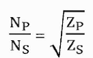
Because of this ability to match impedances, the impedance-matching transformer is widely used in electronic equipment.
Isolation Transformers
Aside from the ability to easily convert between different levels of voltage and current in AC and DC circuits, transformers also provide an extremely useful feature called isolation, which is the ability to couple one circuit to another without the use of direct wire connections.
An isolation transformer is a transformer, often with symmetrical windings, which is used to decouple two circuits. An isolation transformer allows an AC signal or power to be taken from one device and fed into another without electrically connecting the two circuits. Isolation transformers block transmission of DC signals from one circuit to the other, but allow AC signals to pass. They also block interference caused by ground loops. Isolation transformers with electrostatic shields are used for power supplies for sensitive equipment such as computers or laboratory instruments.
In electronics testing, troubleshooting and servicing, an isolation transformer is a 1:1 power transformer which is used as a safety precaution. Since the neutral wire of an outlet is directly connected to ground, grounded objects near the device under test (desk, lamp, concrete floor, oscilloscope ground lead, etc.) may be at a hazardous potential difference with respect to that device. By using an isolation transformer, the bonding is eliminated and the shock hazard is entirely contained within the device.
Current Transformers
The Current Transformer (CT) is a step-up device (with respect to voltage), which is what is needed to step down the power line current. Quite often, CTs are built as donut-shaped devices through which the power line conductor is run. Some CTs are made to hinge open, allowing insertion around a power conductor without disturbing the conductor at all.
The industry standard secondary current for a CT is a range of 0 to 5 amps AC. Like Power Transformers, CTs can be made with custom winding ratios to fit almost any application. Because their "full load" secondary current is 5 amps, CT ratios are usually described in terms of full-load primary amps to 5 amps, like this:

Because CTs are designed to be powering ammeters, which are low-impedance loads, and they are wound as voltage step-up transformers, they should never be operated with an open-circuited secondary winding. Failure to heed this warning will result in the CT producing extremely high secondary voltages, dangerous to equipment and personnel alike.
Linear Variable Differential Transformers
A Linear Variable Differential Transformer (LVDT) has an AC driven primary wound between two secondaries on a cylindrical air core form. A movable ferromagnetic slug converts displacement to a variable voltage by changing the coupling between the driven primary and secondary windings. The LVDT is a displacement or distance measuring transducer. Units are available for measuring displacement over a distance of a fraction of a millimetre to half a meter. LVDT's are rugged and dirt resistant compared to linear optical encoders.
FIGURE
The excitation voltage is in the range of 0.5 to 10 VAC at a frequency of 1 to 200 KHz. A ferrite core is suitable at these frequencies. It is extended outside the body by a nonmagnetic rod. As the core is moved toward the top winding, the voltage across this coil increases due to increased coupling, while the voltage on the bottom coil decreases. If the core is moved toward the bottom winding, the voltage on this coil increases as the voltage decreases across the top coil. Theoretically, a centred slug yields equal voltages across both coils. In practice leakage inductance prevents the null from dropping all the way to 0V.
With a centred slug, the series-opposing wired secondaries cancel yielding V13 = 0. Moving the slug up increases V13. Note that it is in-phase with V1, the top winding, and 180° out of phase with V2, bottom winding. Moving the slug down from the centre position increases V13. However, it is 180° out of phase with V1, the top winding, and in phase with V2, bottom winding. Moving the slug from top to bottom shows a minimum at the centre point, with a 180° phase reversal in passing the centre.
Three-phase Transformers
Since three-phase is used so often for power distribution systems, it makes sense that we would need three-phase transformers to be able to step voltages up or down. This is only partially true, as regular single-phase transformers can be ganged together to transform power between two three-phase systems in a variety of configurations, eliminating the requirement for a special three-phase transformer. However, special three-phase transformers are built for those tasks, and are able to perform with less material requirement, less size, and less weight than their modular counterparts.
A three-phase transformer is made of three sets of primary and secondary windings, each set wound around one leg of an iron core assembly. Essentially it looks like three single-phase transformers sharing a joined core.
FIGURE
Those sets of primary and secondary windings will be connected in either Δ or Y configurations to form a complete unit. The various combinations of ways that these windings can be connected together in will be the focus of this section.
Whether the winding sets share a common core assembly or each winding pair is a separate transformer, the winding connection options are the same:

The reasons for choosing a Y or Δ configuration for transformer winding connections are the same as for any other three-phase application: Y connections provide the opportunity for multiple voltages, while Δ connections enjoy a higher level of reliability (if one winding fails open, the other two can still maintain full line voltages to the load).
FIGURE
A three phase transformer is effectively the same as three single-phase transformers connected in a three-phase arrangement and it is possible to use three separate single phase transformers, although it is far more usual to have all the windings on the same core. Three-phase transformers have six windings, three primary and three secondary, that can be connected in star (Y) or delta (D) configurations. The primary winding is commonly denoted by a capital Y or D and the secondary windings are denoted by a lower case y or d.
Part (a) from the above figure shows a transformer where both primary and secondary windings are star connected, such a transformer is called a star-star, wye-wye or Yy transformer. Part (b) shows a delta-delta, mesh-mesh or Dd transformer, where both primary and secondary cores are delta connected. The figure shows the standard method for marking three-phase transformer windings. The three primary windings are labelled with a capital A, B and C. The three secondary windings are labelled with a lower case a, b and c. Each winding has two ends and labelled 1 and 2 so that the ends of the primary on the second winding are labelled B1 and B2.
The secondary and primary coils need not be connected in the same configuration so that star-delta (Yd) and delta-star (Dy) are also possible and are shown in the figure below. Transformers with delta connected secondaries are seldom used to supply consumer's loads because there is no position for a neutral wire, such transformers are used for high voltage transmission between substations.
FIGURE
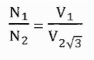
If the primary and secondary windings are connected similarly (i.e. star-star or delta-delta), calculations are the same as those for single phase transformers, as long as the system is balanced. When the primary and secondary have different types of connection, the overall turns ratio of the transformer is more complicated. For example, consider a single phase transformer with a 1:1 turns ratio, the input and output voltages from the windings are the same. This will also be true for a three-phase transformer with the primary and secondary windings connected similarly. However, if the three-phase transformer is connected in star-delta and has a primary line voltage of V, each of the star connected primaries will have the phase voltage across it, which is V/V3 (the voltage between any line and the neutral point).
Each of the secondary windings will then have this same voltage induced in it, and since these windings are delta-connected, the voltage V/V3 will be the secondary. Thus, a star-delta transformer with a turns ratio of 1:1 provides a V3:1 step-down. Thus, from figure (a):
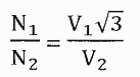
For a delta-star transformer a similar effect happens but there is a 1: square root 3 step-up for line voltage in addition to the effect of the turns. Thus, from figure (b):
Only identical transformers should ever be connected in parallel. Transformers are identical when their turn ratios are the same and when the primary and secondary windings are connected in the same way.